The ECG (Electrocardiogram) sensor is an electronic module designed to measure and monitor the heart's electrical activity. These sensors detect biopotential signals generated by the heart via electrodes placed on the body, process these signals by amplifying, filtering, and converting them into a format readable by a microcontroller (e.g., Arduino). Commonly used in hobby electronics, biomedical projects, and educational applications, these sensors provide a practical tool for understanding the basic operating principles of professional medical devices. By measuring the low-amplitude electrical potential differences that arise during each contraction and relaxation of the heart muscle, they enable the acquisition of information about heart rate and rhythm.
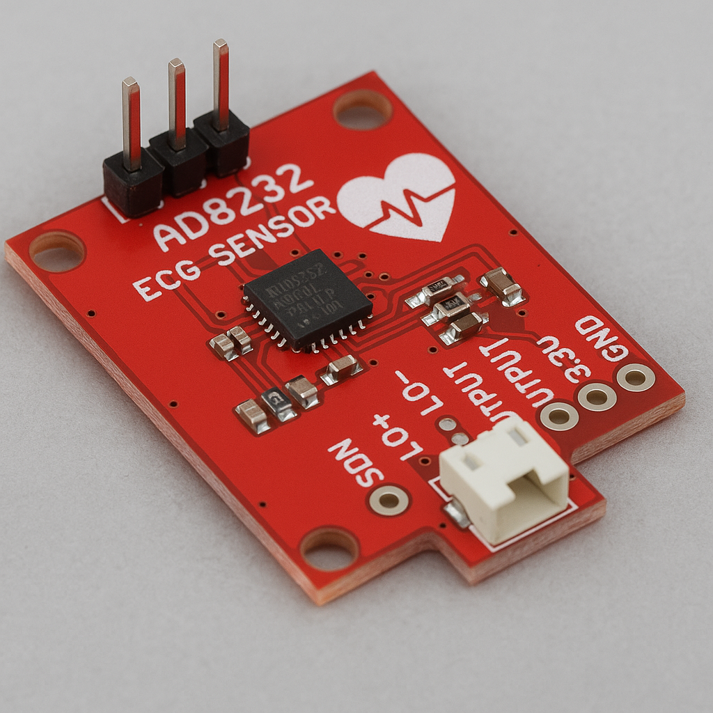
AD8232 ECG SENSOR (Generated by Artificial Intelligence)
Working Principle
The working principle of an ECG sensor can fundamentally be examined in three stages: signal detection, signal processing (amplification and filtering), and data transfer to the microcontroller. The heart operates with an electrical impulse system that starts in the sinoatrial node and spreads throughout the entire heart muscle. This electrical activity creates potential differences on the body surface at very low voltage levels (in the millivolt-microvolt range). The primary task of an ECG sensor is to purify these weak signals from environmental noise and convert them into meaningful data.
Signal Detection with Electrodes
The measurement of the ECG signal is performed via electrodes attached to specific points on the body. Typically, a three-electrode configuration is used: two measurement electrodes and one reference (ground) electrode. Similar to Einthoven's triangle principle, these electrodes are usually placed on both arms and one leg (typically the right leg). The measurement electrodes detect the potential difference on the body surface. The reference electrode, using a technique known as the "Driven Right Leg" (DRL) circuit, is used to suppress common-mode noise (e.g., 50/60 Hz power line noise) on the body. This is a critical step that significantly improves signal quality.
Signal Processing: Amplification and Filtering
The raw ECG signal obtained from the body is quite weak and susceptible to noise. Therefore, it needs to undergo a series of processes to be handled by a microcontroller.
Instrumentation Amplifier
The detected raw signal first enters an instrumentation amplifier (INA) stage. Instrumentation amplifiers are known for having a high common-mode rejection ratio (CMRR). Thanks to these features, they effectively suppress noise signals common to both measurement electrodes, while amplifying the very small potential difference between them (i.e., the ECG signal) thousands of times (typically 1000x or more). Special integrated circuits are used for this process in popular ECG sensor modules like the AD8232.
Filtering Stages
The amplified signal may still contain various noise components. To clean these noises, the sensor module includes various filter circuits:
- High-Pass Filter: This filter blocks low-frequency noises (typically below 0.5 Hz) caused by factors such as electrode-skin contact and patient movements. These noises are known as "baseline wander" and cause the ECG graph to slowly drift on the vertical axis.
- Low-Pass Filter: Used to eliminate high-frequency noises caused by muscle contractions and external electronic devices. It is usually set to a cutoff frequency between 40 Hz and 150 Hz. This ensures the preservation of the fundamental components of the ECG signal while filtering out unwanted noises.
- Notch Filter: This is a narrow-band filter specifically designed to suppress power line noise at 50 Hz or 60 Hz. This noise is one of the most common and bothersome sources of interference.