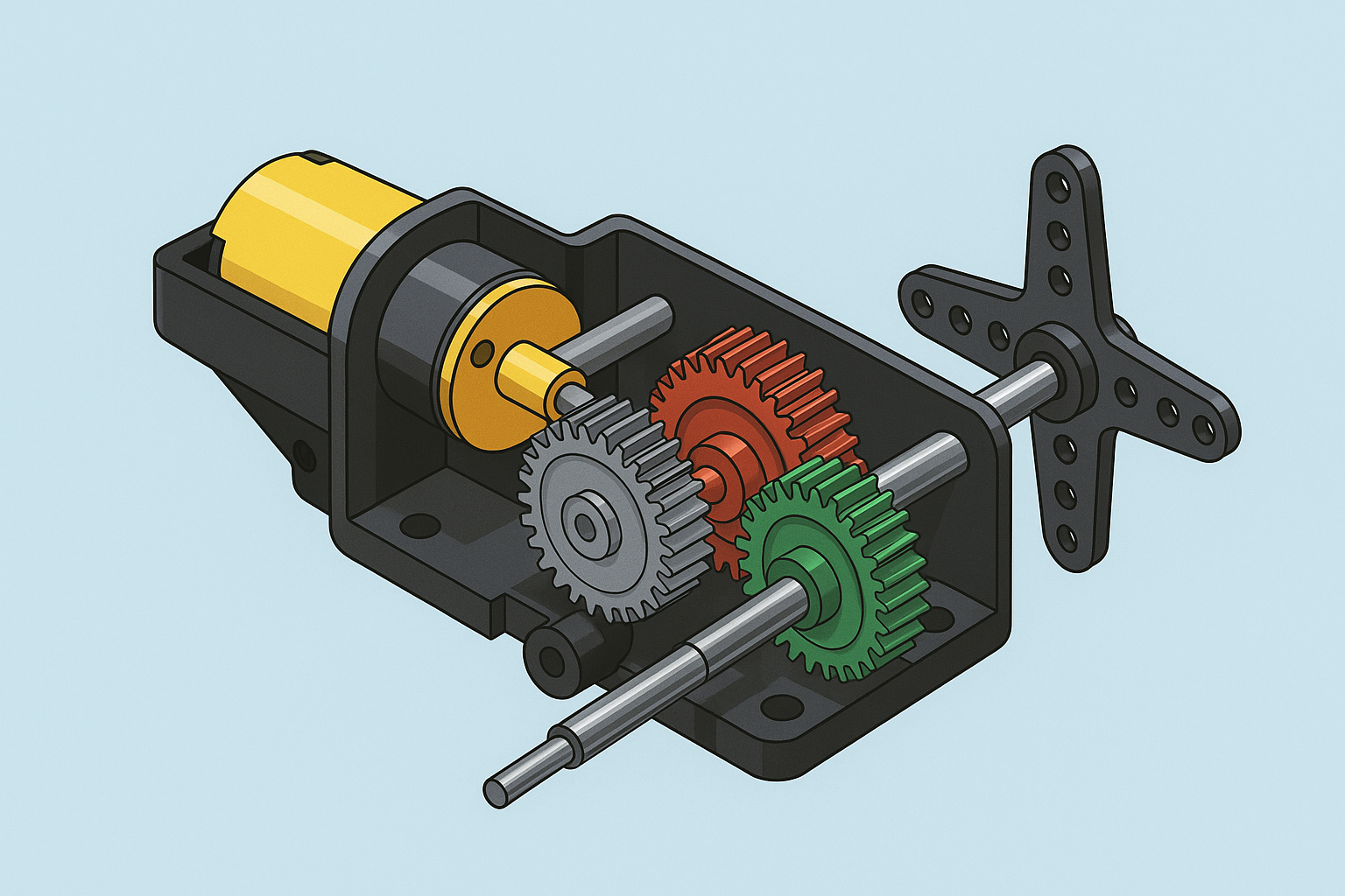
A servo motor is a closed-loop system that enables precise control of mechanical movement in automatic control systems. These motors allow for angular or linear position, speed, and acceleration control, maintaining the target position with high accuracy thanks to a feedback mechanism. They are widely used in industrial robots, RC (radio-controlled) vehicles, CNC machines, and automation systems.
 Servo Motor Internal Structure (Created with Artificial Intelligence)
History
The foundation of servo motors dates back to hydraulic systems in the 19th century. The first electric servo motor was developed in the 1920s by John C. Stevens. During World War II, their use expanded in artillery systems and radar antennas. With the advancement of microprocessor technology in the 1970s, modern servo motors became standard in industrial production lines.
Components
Motor
- Consists of DC (direct current) or AC (alternating current) motors.
- DC servo motors are used in small-scale applications, while AC servo motors are preferred in industrial systems.
- The motor's rotation speed and torque are adjusted via control signals.
Feedback Sensor
- Sensors such as potentiometers, encoders, or resolvers measure the real-time position of the motor shaft.
- Potentiometers are commonly used in hobby servo motors, whereas magnetic encoders are preferred in industrial systems.
- The sensor data is transmitted to the control circuit to calculate the error signal.
Control Circuit
- Comprises microcontrollers or dedicated driver boards.
- Compares the input signal with feedback data and optimizes motor movement using PID (Proportional-Integral-Derivative) algorithms.
Gearbox
- Reduces the motor's high speed while increasing torque.
- Made of plastic or metal gears, ensuring durability and quiet operation.
Working Principle
Servo motors are controlled via PWM (Pulse Width Modulation) signals. The control signal consists of electrical pulses repeated at specific intervals. The pulse width determines the motor's target position:
Example PWM Values
- 1 ms pulse width → 0° (minimum position),
- 1.5 ms pulse width → 90° (neutral position),
- 2 ms pulse width → 180° (maximum position).
The motor processes the incoming signal every 20 ms. The feedback sensor continuously measures the shaft's position. The control circuit moves the motor until the difference (error signal) between the target and current position is minimized. This closed-loop system ensures precision and stability.
Types of Servo Motors
Positional Rotation Servo
- Limited movement capability between 0° and 180°.
- Used in RC vehicle steering and throttle control.
Continuous Rotation Servo
- Capable of 360° free rotation.
- Pulse width determines the direction and speed (e.g., robot wheels).
Linear Servo
- Provides linear motion instead of rotational movement.
- Preferred in industrial arms and valve controls.
AC and DC Servo Motors
- AC Servo: Used in industrial applications requiring high power and speed (e.g., conveyor belts).
- DC Servo: Common in hobby projects due to low cost and compact design.
Applications
- Robotics: Controlling joint movements in robotic arms.
- Aviation: Flap and landing gear control in UAVs (drones).
- Automation: Packaging machines, 3D printers, and CNC machines.
- Consumer Electronics: Camera autofocus systems and solar panel sun tracking.
Advantages and Disadvantages
Advantages | Disadvantages |
High torque and precision | More expensive than standard motors |
Energy efficient | Requires complex control circuitry |
Wide speed range | Maintenance needed due to gear wear |

