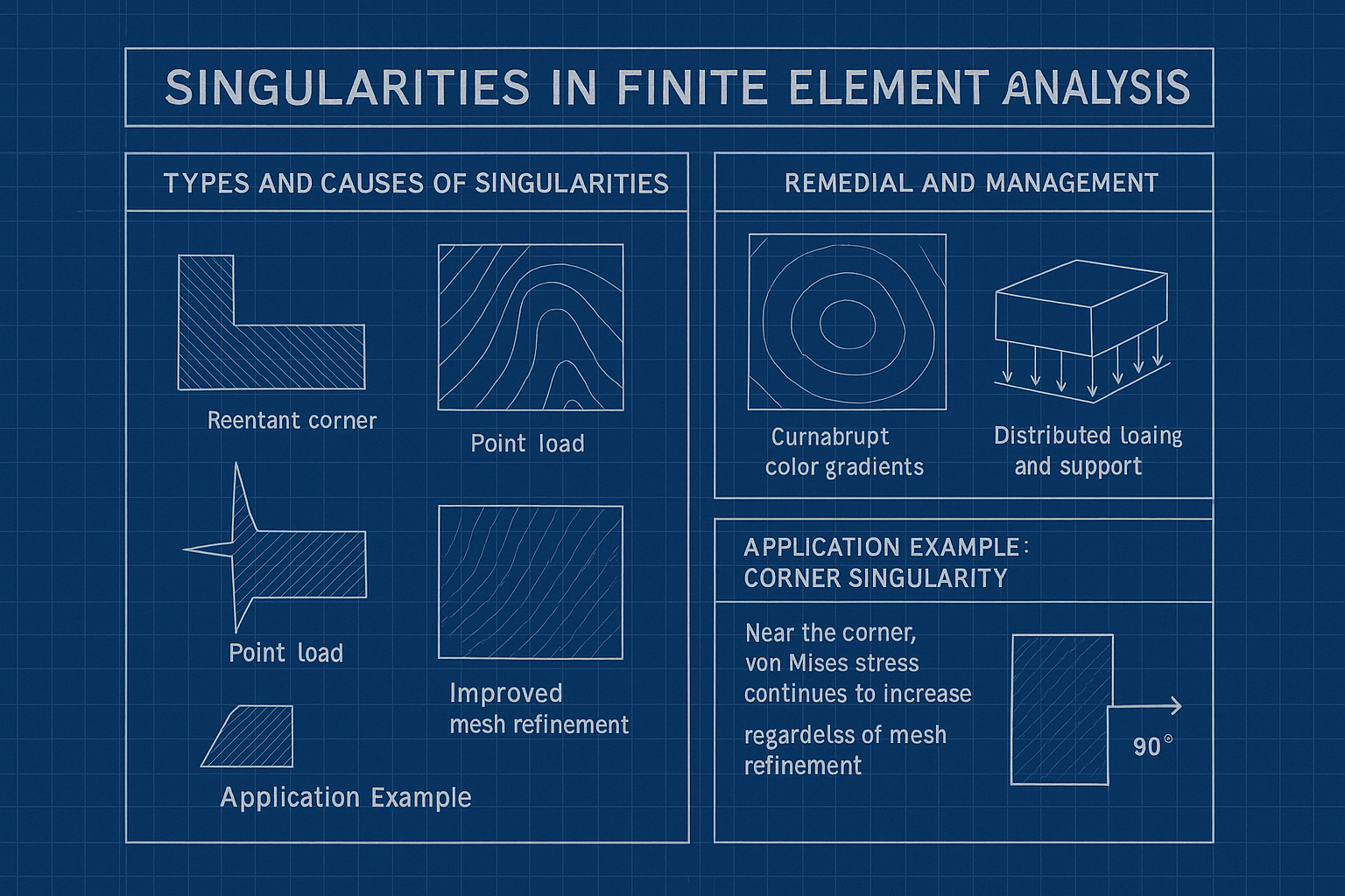
The Finite Element Method (FEM) is a numerical technique widely used in the analysis of systems with discontinuities or complex geometries. However, in certain cases, FEM may produce unphysically large results, which are commonly referred to as singularities. A singularity occurs when certain points in the solution domain theoretically reach infinite values. At this stage, the mathematical solution loses its validity, and a deviation from the physical behavior of the system is observed. In FEM, singularities typically arise due to modeling assumptions, mesh topology, or boundary conditions.

Blueprint shows FEM stress singularities. (Generated by AI)
Typey and Causes of Singularities
Singularities in finite element analysis (FEA) are localized regions where stress or strain values tend to become infinite or fail to converge as the mesh is refined. These arise from several distinct sources. Geometric singularities occur near sharp features in a model, such as reentrant corners (interior angles less than 90°) and pointed tips. These areas concentrate stress heavily, particularly in two-dimensional analyses, and generate non-physical stress intensities as mesh density increases.
Load and constraint singularities emerge from idealized boundary conditions. Applying a load or constraint to a single node results in an unrealistic concentration of force or stiffness, leading to infinite stress values. These are modeling artifacts and do not reflect real-world physical behavior.
Material discontinuity singularities develop at the interfaces between materials with significantly different mechanical properties. If stress continuity is not properly enforced at such junctions—for example, at a steel–aluminum boundary—sharp transitions in stiffness can cause local singularities.
Mesh-induced singularities, while not physical in nature, can mimic the behavior of real singularities. These result from abrupt changes in mesh density, poorly shaped elements, or high aspect ratios that cause numerical instabilities and exaggerated stress gradients.
Indicators of Singularities
Singularities can often be identified through specific patterns in the analysis results. A major sign is the non-converging increase in local stress values, such as Von Mises stress, as the mesh becomes finer. If the stress continues to rise without stabilizing, a singularity is likely present.
Visual clues in stress contour plots can also indicate singularities. These include abrupt, highly localized color transitions that persist regardless of mesh refinement. Another common indicator is the presence of unrealistically high stress values, often exceeding the physical limits of the material (e.g., greater than 10⁶ MPa), which are not feasible under real loading conditions.
From a numerical perspective, divergence in strain energy or other energy norms with increasing mesh resolution also signals a singularity. These issues compromise the validity of local stress results and may distort global response interpretations.
Remedial and Management Strategies
Mitigating singularities requires a combination of geometric redesign, modeling refinement, and careful result interpretation. Geometric modification is often the first step: replacing sharp corners with fillets or chamfers and smoothing pointed features reduces stress concentrations.
To address loading artifacts, idealized point loads and constraints should be replaced with distributed loads and supports over a region. This ensures more realistic simulation of physical conditions and minimizes artificial stiffness or force intensities.
Mesh quality enhancement plays a critical role. Using local mesh refinement in high-stress regions and employing higher-order elements (such as quadratic elements) can improve solution accuracy and reduce sensitivity to singular behaviors.
Finally, in regions where singularities cannot be completely removed, careful interpretation is essential. Relying on elemental average values or Gauss point data instead of nodal stresses provides more stable and meaningful results. It is also advisable to evaluate quantities like stress gradients, strain energy densities, or force-displacement curves rather than focusing solely on peak stress values, which may be unreliable near singularities.
Application Example: Corner Singularity
In an FEM analysis where a tensile load is applied to a plate with a 90° reentrant corner:
- Regardless of mesh refinement, Von Mises stress continues to increase near the corner.
- The stress field becomes highly localized and loses its physical interpretation in that region.
- This highlights a mathematical limitation of the solution; however, the FEM results typically remain consistent elsewhere in the domain.
Interpretation of FEM Singularities
Singularities in FEM are usually not caused by physical irregularities in the structural system but rather stem from the limitations of numerical modeling. Therefore, singularities should not be interpreted as a failure of the method itself, but rather as indicators of the boundaries of its applicability. In reality, mechanisms such as plastic deformation and microcrack propagation prevent the exact occurrence of such idealized conditions.

