This article was automatically translated from the original Turkish version.
+2 More
Type(s) | Cable-stayed Bridge | ||||||||
|---|---|---|---|---|---|---|---|---|---|
Location | Tarn Valley France | ||||||||
Usage | Road Bridge | ||||||||
Opening Year | 2004 | ||||||||
Pier Material | High-Performance Concrete | ||||||||
Superstructure Material | Steel Deck | ||||||||
Pier Height | 78 m – 245 m Range | ||||||||
Number of Piers | 7 | ||||||||
Main Spans | 8 Spans | ||||||||
Total Length | 2,460 m | ||||||||
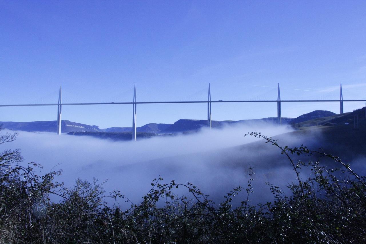
Millau Viaduct is a multi-span cable-stayed highway bridge located over the Tarn Valley in the Occitanie region of France. It forms the most critical crossing on the A75 highway, enabling uninterrupted travel between Clermont-Ferrand and Béziers. The structure, which connects the two sides of the valley with a slender steel deck supported by tall concrete piers, has been a symbolic representation of modern engineering and architectural design since its opening.

Millau Viaduct (Pexels)
The design of the Millau Viaduct was developed with careful consideration of the Tarn Valley’s topography. The project was conceived by British architect Norman Foster and French engineer Michel Virlogeux. The structure follows the multi-span cable-stayed bridge typology, with the load-bearing system serving as the primary determinant of its architectural composition. Inverted-Y-shaped steel pylons, mounted on twin-shell concrete piers, support the steel deck via cables. The slender deck and overhead suspension system create a regular rhythm between the vertical and horizontal elements. The combined use of concrete and steel was chosen both to meet structural requirements and to achieve a cohesive structural expression. The design approach shaped the long highway crossing to integrate seamlessly within the valley’s natural silhouette.
The construction of the Millau Viaduct began after an extended period of planning and preparation. Technical, financial, and administrative arrangements were completed during the development phase, and the implementation phase was carried out over approximately three years. An organizational structure was established involving experts from multiple disciplines, with hundreds of personnel working simultaneously during peak periods. Construction proceeded in stages: the fabrication of concrete piers, the assembly of the steel deck, and the installation of the cable system were completed in a defined sequence. Deck segments were incrementally positioned using a launching method, with low-friction materials applied to sliding surfaces. Concrete pours were executed in large volumes without interruption, using high-strength materials. Wind conditions and the valley’s topographic features were taken into account during construction, leading to the implementation of both temporary and permanent structural measures. The construction process was finalized with load tests and control measurements, after which the structure was opened to service.
The Millau Viaduct features a load-bearing system based on the multi-span cable-stayed bridge typology. Its structural logic relies on transmitting vertical loads through the concrete piers to the ground and transferring deck loads to the pylons via cables. The steel deck is designed as a continuous system along its longitudinal axis, while the cable arrangement ensures balanced load distribution across the spans. The concrete piers and their steel pylons function as an integrated unit, providing both vertical load capacity and stability against lateral forces. A balance between rigidity and flexibility was maintained among the system’s components, with material selection and cross-section design determined accordingly. The structure was designed to withstand service and ultimate load conditions, exhibiting a unified structural integrity under various load combinations.
The superstructure of the Millau Viaduct is based on an orthotropic steel deck system. The deck, with a total length of 2,460 metres, is designed as a continuous beam system with eight spans. The central spans are wider, tapering to shorter spans toward the ends. The approximately 32-metre-wide deck is configured to accommodate two-way highway traffic and emergency lanes.【1】 The closed-box steel system, composed of longitudinal main girders and transverse beams, enables load transfer in both longitudinal and transverse directions. Steel elements were fabricated in workshops, assembled on site, and incrementally launched over the piers using the launching method.

Millau Viaduct (Pixabay)
The deck is supported by multiple suspension cables symmetrically arranged above each pylon. Cables transfer vertical loads from the superstructure to the pylons and then to the concrete piers. The amount of steel used in the superstructure amounts to tens of thousands of tonnes, with assembly operations conducted at high elevations. The closed-box, thin-geometry form provides torsional rigidity while ensuring aerodynamic behavior against wind forces. This system offers an integrated superstructure solution combining the continuous beam arrangement with the cable-stayed load transfer principle.
The superstructure of the Millau Viaduct is supported by seven concrete piers placed at the base of the valley. Pier heights vary according to topography, with the tallest reaching approximately 245 metres and the shortest about 78 metres.【2】 The piers are designed as twin-shell reinforced concrete sections and constructed using high-strength B60 class concrete. Each pier terminates at the top with a pier cap, forming the connection plane for the steel pylons. Vertical prestressing cables are installed in the pier caps, with eight bundles of 19T15s-type cables placed in each. This arrangement controls compressive stresses and preserves section integrity.
Above the concrete piers stand steel pylons that are 87 metres high.【3】 These inverted-Y-shaped pylons serve as the primary load-bearing elements to which the suspension cables are attached. Multiple cable bundles are symmetrically positioned on either side of each pylon, transmitting loads from the deck to the pylons. The total height from the top of the pylons to the lowest point of the valley reaches approximately 343 metres.【4】 The steel pylons are fixed to the pier caps using specialized connection elements and steel “spider” details. This system is designed to balance not only vertical load transfer but also lateral and torsional forces.
The foundation system of the Millau Viaduct is based on a piled raft arrangement. Each concrete pier rests on four large-diameter piles, with diameters ranging from approximately 4.5 to 5 metres. Pile depths vary between 9 and 16 metres depending on the geological characteristics of the ground. The raft slabs above the foundations are designed with thicknesses between 3 and 5 metres. In some piers, particularly those located over marl layers, the pile tips are expanded to create base diameters of approximately 7 metres. This modification increases load distribution area and enhances bearing capacity.【5】
Ground profile consists of limestone and marl units. The rock mass quality index for limestone layers averages around 65, while for marl units it is approximately 53. Ground properties were decisive in foundation design; pile load transfer ratios varied according to soil type. In limestone, approximately 35 percent of the load is transferred along the pile shaft, whereas in marl units this ratio reaches approximately 90 percent. Settlement and rotation values were continuously monitored during construction, with total settlement not exceeding 5 millimetres. This system was designed to safely transfer vertical and lateral loads from the superstructure to the ground.【6】
Millau Viaduct (Pixabay)
The Millau Viaduct is operated with consideration of the Tarn Valley’s topographic and climatic conditions. Wind speeds in the valley occasionally approach 200 kilometres per hour; traffic flow is controlled when certain threshold values are exceeded.【7】 The aerodynamic cross-section geometry and rigidity of the superstructure contribute to limiting wind-induced vibrations. The structure undergoes longitudinal displacement due to temperature variations, accommodated by expansion and support arrangements. Load tests and measurements conducted after construction confirmed the structure’s performance under environmental conditions.
Bridge provides a continuous transportation link on the A75 highway, enabling direct road access between inland France and the Mediterranean coast. The two-way highway configuration serves daily vehicle traffic. In addition to its transportation function, the structure is accessible to visitors through exhibition areas and guided routes. Approximately 200,000 people annually observe or visit the bridge from various vantage points.【8】 In this regard, the viaduct also serves as a regional cultural landmark beyond its function as infrastructure.
Calamoneri, C., T. Duclos, P. Ello, B. Gausset, Z. Hajar, P. K. Ly, A. Simon, J. Vassord, and M. Virlogeux. “Millau viaduct: Detailed design of concrete piers.” Concrete Structures: the Challenge of Creativity. Association Française de Génie Civil (AFGC). Accessed February 18, 2026. https://www.afgc.asso.fr/app/uploads/2018/05/104-Hajar.pdf
France.fr. “7 chiffres à connaître sur le Viaduc de Millau.” Accessed February 18, 2026. https://www.france.fr/fr/article/viaduc-millau/
GLM35. “Viyadük Millau Uçak Görünümü görseli.” Pixabay. Accessed February 18, 2026. https://pixabay.com/tr/photos/viyad%c3%bck-millau-u%c3%a7ak-g%c3%b6r%c3%bcn%c3%bcm%c3%bc-fransa-351087/
Juv. "Photo: Light, Bright, Clear, Soft." Pexels. Accessed February 18, 2026. https://www.pexels.com/tr-tr/fotograf/isik-parlak-acik-hafif-6279201/
Le Viaduc de Millau. "Le Viaduc – Présentation du Viaduc." Le Viaduc de Millau. Eiffage. Accessed February 18, 2026. https://www.leviaducdemillau.com/accueil-viaduc-de-millau/le-viaduc/le-viaduc-presentation-du-viaduc.html
Lin, Xiangchen. “Construction Processes and Strategies of Millau Viaduct.” *Highlights in Science, Engineering and Technology* 18 (2022): 86-92. Darcy & Roy Press. Accessed February 18, 2026. https://drpress.org/ojs/index.php/HSET/article/view/2579
Maelledivet. “Sabah Bağlantı Noktası Millau görseli.” Pixabay. Accessed February 18, 2026. https://pixabay.com/tr/photos/sabah-ba%c4%9flant%c4%b1-noktas%c4%b1-millau-2096668/
Schlosser, F., Servant, A., Guilloux, A., and A. Bergere. "Millau viaduct geotechnical studies and foundations." *Journal of Rock Mechanics and Geotechnical Engineering* 5, no. 3 (2013): 243–247. Accessed February 18, 2026. https://www.sciencedirect.com/science/article/pii/S167477551300036X
SchrijverijDrenthe. “Millau Viaduct, Summer, Natural Landscape.” Pixabay. Accessed February 18, 2026. https://pixabay.com/tr/photos/millau-viyad%c3%bc%c4%9f%c3%bc-yaz-tatil-fransa-908320/
SlimMars 13. "Photo: Free open air, open view, infrastructure, terrain, and cable bridge." Pexels. Accessed February 18, 2026. https://www.pexels.com/tr-tr/fotograf/fransa-mimari-altyapi-kablolu-kopru-12916282/
Viaduc de Millau. "Les chiffres clés." *Le Viaduc de Millau.* Eiffage. Accessed February 18, 2026. https://www.leviaducdemillau.com/accueil-viaduc-de-millau/le-viaduc/les-chiffres-cles.html
Viaduc de Millau. "Les femmes et les hommes de l’exploitation." *Le Viaduc de Millau.* Eiffage. Accessed February 18, 2026. https://www.leviaducdemillau.com/accueil-viaduc-de-millau/le-viaduc/le-viaduc-les-femmes-et-les-homm.html
Viaduc de Millau. "Les métiers de la construction." Le Viaduc de Millau. Eiffage. Accessed February 18, 2026. https://www.leviaducdemillau.com/accueil-viaduc-de-millau/le-viaduc/le-viaduc-les-femmes-et-les-ho-1.html
Viaduc de Millau. "Les étapes de construction." *Le Viaduc de Millau.* Eiffage. Accessed February 18, 2026. https://www.leviaducdemillau.com/accueil-viaduc-de-millau/le-viaduc/les-etapes-de-construction.html
[1]
Viaduc de Millau, “Les chiffres clés,” Le Viaduc de Millau Eiffage, Son Erişim: 18 Şubat 2026, https://www.leviaducdemillau.com/accueil-viaduc-de-millau/le-viaduc/les-chiffres-cles.html
[2]
C. Calamoneri, T. Duclos, P. Ello, B. Gausset, Z. Hajar, P. K. Ly, A. Simon, J. Vassord ve M. Virlogeux, “Millau viaduct : Detailed design of concrete piers,” Concrete Structures: the Challenge of Creativity, Association Française de Génie Civil (AFGC), syf. 1, Son Erişim: 18 Şubat 2026, https://www.afgc.asso.fr/app/uploads/2018/05/104-Hajar.pdf
[3]
Viaduc de Millau, “Les chiffres clés,” Le Viaduc de Millau Eiffage, Son Erişim: 18 Şubat 2026, https://www.leviaducdemillau.com/accueil-viaduc-de-millau/le-viaduc/les-chiffres-cles.html
[4]
A.e.,
[5]
C. Calamoneri, T. Duclos, P. Ello, B. Gausset, Z. Hajar, P. K. Ly, A. Simon, J. Vassord ve M. Virlogeux, “Millau viaduct : Detailed design of concrete piers,” Concrete Structures: the Challenge of Creativity, Association Française de Génie Civil (AFGC), syf. 4, Son Erişim: 18 Şubat 2026, https://www.afgc.asso.fr/app/uploads/2018/05/104-Hajar.pdf
[6]
F. Schlosser, C. Servant, A. Guilloux ve A. Bergere, “Millau viaduct geotechnical studies and foundations,” Journal of Rock Mechanics and Geotechnical Engineering 5, no. 3 (June 2013): 243–245, Son Erişim: 18 Şubat 2026, https://www.sciencedirect.com/science/article/pii/S167477551300036X
[7]
France.fr, “Viaduc de Millau, 7 chiffres à connaître sur un ouvrage de légende,” France.fr, Son Erişim: 18 Şubat 2026, https://www.france.fr/fr/article/viaduc-millau/
[8]
A.e.,
Type(s) | Cable-stayed Bridge | ||||||||
|---|---|---|---|---|---|---|---|---|---|
Location | Tarn Valley France | ||||||||
Usage | Road Bridge | ||||||||
Opening Year | 2004 | ||||||||
Pier Material | High-Performance Concrete | ||||||||
Superstructure Material | Steel Deck | ||||||||
Pier Height | 78 m – 245 m Range | ||||||||
Number of Piers | 7 | ||||||||
Main Spans | 8 Spans | ||||||||
Total Length | 2,460 m | ||||||||
Architectural Design
Construction Process
Load-Bearing System
Superstructure
Piers and Pylons
Foundation System and Ground
Environmental Impact and Usage
