This article was automatically translated from the original Turkish version.

Resistance
Area(s) of Use | Regulator Circuit Amplifier Circuit Power Electronics | ||||||||
|---|---|---|---|---|---|---|---|---|---|
Resistance is defined as the opposition encountered by an electric current flowing through a conductor in electricity circuits. The unit of resistance is the ohm (Ω). It is represented by the letter R in circuits, and two different symbols for it are shown in Figure 1.

What Are the Types of Resistors?
Resistors are fundamental components used in electronic circuits common and come in various types. Generally, resistors are classified into three categories: fixed resistors, variable resistors, and special-purpose resistors.
Fixed resistors have a specific ohmic value and do not vary. They are commonly used in circuits to maintain a constant current or to limit tension. When purchasing these resistors, selection is made based on their power rating (Watt).
Variable resistors, as the name suggests, allow the user to adjust the resistance value according to their needs. Potentiometers and trimpots are common examples of this type and are used in many applications ranging from volume control to precise adjustments.
Special-purpose resistors are sensitive to environmental or electrical variables. They respond to changes in temperature, light, or voltage to provide protection, measurement, or control functions in circuits. For example, NTC/PTC thermistors are sensitive to temperature, LDRs to light, and varistors to voltage changes. These different types of resistors play essential roles in ensuring the safe and efficient operation of electronic circuits important.
Resistor Color Code Calculation
The resistor color code is a system used to determine the resistance value through colored bands printed on the resistor. In this system, each color corresponds to a specific number and is typically used in 4-band, 5-band, or 6-band configurations. The first two or three bands indicate the resistance value, the next band represents the multiplier, and the final band indicates the tolerance. For example, a resistor with brown (1), black (0), and red (×100) bands has a value of 10 × 100 = 1000 Ω (1 kΩ). The color code enables quick reading of resistor values and facilitates electronic circuit design. Figure 2 shows the resistor color code chart.

Figure 2. Resistor Color Code Chart
Resistor Calculation
Series and parallel resistor calculations are fundamental methods used to determine the total resistance in circuits. In series-connected resistors, the total resistance (Rₜ) equals the sum of all individual resistances: Rₜ = R₁ + R₂ + R₃ + .... While the current remains the same through all resistors, the voltage is divided across each one. In parallel-connected resistors, the total resistance is equal to the reciprocal of the sum of the reciprocals of the individual resistances: 1/Rₜ = 1/R₁ + 1/R₂ + 1/R₃ + .... In parallel connections, the same voltage is applied across all resistors, while the current is divided according to each resistor’s value. These calculations are critical in the design and analysis of circuits. Figures 3 and 4 show parallel and series resistor connections respectively.

Figure 3. Parallel Resistor Connection
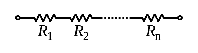
Figure 4. Series Resistor Connection
Boylestad, Robert L., and Louis Nashelsky. Electronic Devices and Circuit Theory. 11th ed. Boston: Pearson, 2015.
Horowitz, Paul, and Winfield Hill. The Art of Electronics. 3rd ed. New York: Cambridge University Press, 2015.
Malvino, Albert Paul, and David J. Bates. Electronic Principles. 8th ed. New York: McGraw-Hill Education, 2015.
Sedra, Adel S., and Kenneth C. Smith. Microelectronic Circuits. 7th ed. New York: Oxford University Press, 2015.

Resistance
Area(s) of Use | Regulator Circuit Amplifier Circuit Power Electronics | ||||||||
|---|---|---|---|---|---|---|---|---|---|