


This article was automatically translated from the original Turkish version.
An anechoic chamber is a specialized acoustic test room designed to eliminate echoes or reflections. The term “anechoic,” derived from Greek, means “non-reflective.” These chambers are used primarily to simulate free-field conditions for the propagation of sound and electromagnetic waves. Anechoic chambers serve as essential tools in various industrial tests, research and development processes, and measurements requiring compliance with international standards.
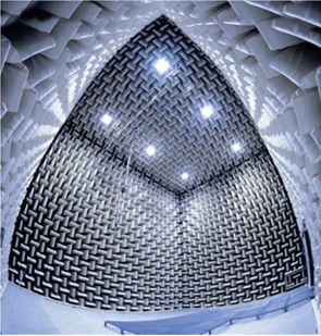
Anekoik Odaya Ait Görsel- TÜBİTAK UME,GEBZE (TÜBİTAK UME)
Anechoic chambers are equipped with high-performance sound and wave absorption materials installed on their interior surfaces. These absorbers are typically wedge-shaped and mounted on all six surfaces (walls, ceiling, and floor), effectively eliminating nearly all reflections from the chamber’s surfaces. The chamber floor is often supported by a transparent platform made of stretched wire mesh; however, semi-anechoic solutions with reflective hard floors are also preferred for practical reasons and to reduce measurement errors.
In the design of sound absorbers, material density and resistance to airflow are critical parameters. To achieve effective absorption at low frequencies, wedge structures may be made multi-layered or incorporate resonator-based designs. For electromagnetic applications, materials such as carbon-loaded foam or ferrite tiles are commonly used.
Anechoic chambers are used for measurements in both acoustic and electromagnetic fields. In acoustic chambers:
RF anechoic chambers used for EMC (Electromagnetic Compatibility) testing are designed to:
Measurements conducted in anechoic chambers are defined by international standards such as ISO 3745 and ANSI S12.35. These standards specify methods for measuring the chamber’s anechoic performance, microphone placement, sound source characteristics, and measurement procedures. The directivity of the sound sources used during chamber validation is critical to the reliability of measurement results.
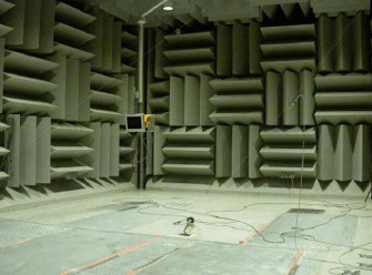
Anekoik Odaya Ait Görsel- İ.T.Ü. OTAM ()
Creating fully anechoic environments is not always necessary and can be costly. Therefore, semi-anechoic chambers with reflective floors are widely used. Such chambers offer a more practical and suitable test environment for measuring devices that interact with the ground, such as washing machines, compressors, and electric tools.
The history of anechoic chambers extends back to the mid-20th century, when radio waves and acoustic properties began to be studied scientifically. With the widespread adoption of EMC regulations in the 1980s, major companies shifted toward constructing chambers to replace open-area test sites. One milestone in this field was the first 3-meter EMC anechoic chamber built for IBM in 1982. From the 1990s onward, the use of ferrite tiles and hybrid absorber materials enabled chambers to become smaller while improving performance.
Measurements in anechoic chambers vary depending on the method used and the size of the test object. The two primary measurement approaches defined by international acoustic standards are:
In both methods, sound power levels are calculated using A-weighted sound pressure levels, octave or 1/3-octave band analyses, and frequency components.
The performance of anechoic chambers depends on the properties of the absorber materials installed on their interior surfaces. The primary purpose of these materials is to absorb sound or electromagnetic waves without reflection. In acoustic anechoic chambers, absorbers typically take the following forms:
Material selection is determined by the target frequency range, chamber size, and test requirements.
The design of an anechoic chamber is determined by parameters such as the target frequency range, required measurement accuracy, and the size of the objects to be tested. Key design criteria include:
All these parameters ensure high-accuracy measurements in both acoustic and electromagnetic testing.
Anechoic chambers are used across various sectors for product development, quality control, and regulatory compliance testing. Each sector may require different types of anechoic chamber solutions based on specific measurement needs. Major application areas include:
These application examples demonstrate that anechoic chambers are not merely academic tools but integral components of product development and certification processes.
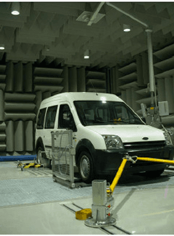
Anekoik Odada Yapılan Araç Testine Ait Görsel ()
In Türkiye, anechoic chamber infrastructure has developed to meet growing testing demands in industry and academic research centers. These chambers enable domestic products to meet the EMC and acoustic compliance requirements necessary for international market acceptance. Examples of key institutions include:
In addition to these institutions, major domestic manufacturers such as Vestel, BSH, and Arçelik also maintain anechoic and semi-anechoic chambers to control the acoustic characteristics of their products. This infrastructure has become an indispensable part of product development, quality control, and compliance evaluation processes.
Dilmen, Hakan. Akustik Ölçüm Odaları ve Endüstriyel Kullanımları. Sunum dosyası, TÜBİTAK UME Akustik Paydaşlar Toplantısı, Gebze, 23 Ocak 2013. Accessed June 16, 2025.
Lawrence, Brian F. "Anechoic Chambers: Past and Present." Conformity Magazine, February 2005. Accessed June 13, 2025.
Schøyen Nielsen, M. B. "Anechoic vs. Semi Anechoic Rooms." Brüel Acoustics, Venlighedsvej 6, 2970 Hørsholm, Denmark. Accessed June 13, 2025.

Structural Features
Applications
Standards and Validation
Semi-Anechoic Chambers
Historical Development
Measurement Methods
Absorber Material Technologies
Anechoic Chamber Design Criteria
Sectoral Application Examples
Institutional Examples in Türkiye