


This article was automatically translated from the original Turkish version.
+1 More
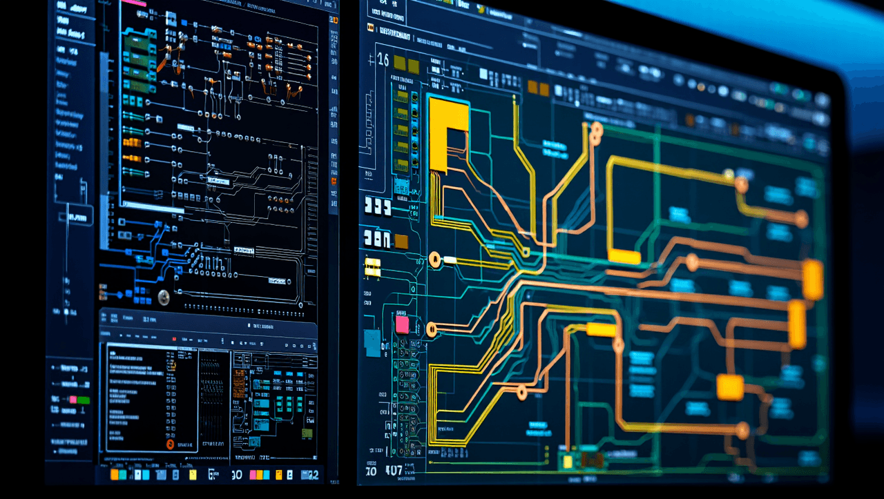
Circuit Design Software (Generated with Artificial Intelligence)
Other Name(s) | Electronic Design Automation (EDA) CAD Software PCB Design Software | ||||||||
|---|---|---|---|---|---|---|---|---|---|
Basic Functions | Schematic capture, PCB layout, simulation, generation of manufacturing files | ||||||||
Basic Simulation Engine | SPICE (Simulation Program with Integrated Circuit Emphasis) | ||||||||
Popular Open-Source Software | KiCad, Fritzing, gEDA | ||||||||
Popular Commercial Software | Altium Designer, Autodesk Eagle, Cadence OrCAD/Allegro, Proteus | ||||||||
Related Field(s) | Electronics engineering embedded systems robotics mechatronics | ||||||||
Circuit design software refers to computer-aided design (CAD) and electronic design automation (EDA) tools used for designing simulating and analyzing electronic circuits. These software enable engineers and designers to create electronic systems such as printed circuit boards (PCBs) and integrated circuits (ICs) in a virtual environment. They significantly accelerate the design process increase efficiency and reduce costs by identifying potential errors before production. These tools are used across a wide spectrum ranging from simple schematic diagrams to the fabrication of complex multilayer high-frequency circuits.
Alongside the development of the electronics industry circuit design software has evolved from basic drawing programs into integrated platforms that include multiple modules such as schematic capture PCB layout component library management circuit simulation and generation of manufacturing files. These software possess the capability to manage the entire workflow of a project from its conceptual stage to final product manufacturing.
Modern circuit design software typically consists of several integrated components that work together to manage different stages of the design process.
This is the first step in the design process. During this phase the logical structure of the circuit is created on a schematic using symbols for electronic components and their interconnections. Schematic editors provide visual tools for connecting component pins net labels and bus structures. The schematic generated at this stage defines the electrical functionality of the circuit and serves as the foundation for PCB layout.
After the schematic is completed the physical printed circuit board is designed. PCB layout editors allow placement of the component footprints from the schematic onto a virtual board and routing electrical connections between them using copper traces. Factors such as layer management component placement optimization and signal integrity are considered during this process.

PCB Design Program - 1 (Generated by Artificial Intelligence)
One of the foundational elements of circuit design software. Libraries contain schematic symbols PCB footprints and sometimes 3D models for thousands of electronic components. Designers can use these prebuilt libraries to accelerate their workflow or create custom components. Effective library management is critical to ensuring the accuracy and consistency of a project.
Many advanced software tools can generate a three-dimensional model of the designed PCB. This feature is used to verify whether the board fits within a mechanical enclosure whether components physically interfere with each other and how the overall assembly will appear. 3D models can be exported to mechanical CAD software to enable comprehensive system integration analyses.
This is an automated process that verifies whether the completed PCB layout complies with manufacturability standards. DRC checks rules defined by manufacturers such as minimum trace spacing trace widths and hole sizes. Software offering real-time DRC alerts designers to potential errors during the design phase thereby improving project quality.
Circuit simulation is the process of analyzing the behavior of an electronic circuit in a virtual environment before physical fabrication. This enables designers to validate performance identify potential issues and optimize the design. Most simulation software is based on the SPICE (Simulation Program with Integrated Circuit Emphasis) engine developed at the University of California Berkeley in the 1970s or its derivatives.
The accuracy of simulation depends directly on the quality of the component models used. Semiconductor manufacturers commonly provide precise SPICE models for their products free of charge. Major types of simulation analyses include:
DC Analysis: Calculates the steady-state DC operating points (voltage and current values) of the circuit.
AC Analysis: Analyzes the circuit’s behavior over a specified frequency range (gain phase shift etc.). Used to examine frequency response of circuits such as filters and amplifiers.
Transient (Time-Domain) Analysis: Examines the circuit’s time-dependent behavior. Used to analyze nonlinear systems such as oscillators switching power supplies and digital circuits.

PCB Design Program - 2 (Generated by Artificial Intelligence)
In addition these software offer more advanced analyses such as Monte Carlo (analyzes the impact of component tolerances) sensitivity (measures how changes in one parameter affect another) and noise (calculates internal noise within the circuit).
Circuit design software can be categorized based on licensing model platform support and target user groups.
Software in this category is typically available at no cost with source code openly accessible. KiCad is the most popular open-source EDA tool offering professional-grade features without any restrictions. Fritzing is especially popular among hobbyists and educators due to its user-friendly interface and virtual breadboard view.
These tools are widely used in professional engineering environments and generally require a license fee. Industry-standard tools such as Altium Designer Cadence OrCAD/Allegro and Siemens PADS provide advanced features comprehensive libraries and technical support for complex and high-speed designs. Some commercial software such as Autodesk Eagle and DipTrace offer limited free versions for students educators and hobbyists to reach a broader audience.
These tools have gained popularity in recent years and operate directly through a web browser without requiring installation. Platforms such as EasyEDA and Upverter enable projects to be stored in the cloud easily shared among team members and collaboratively edited in real time. Such software often integrates with component suppliers and PCB manufacturers to further streamline the design process.
There are numerous circuit design software options available on the market catering to diverse needs. Key examples include:
A powerful EDA tool developed for professional use that integrates schematic capture PCB layout simulation and 3D modeling within a single unified platform.
Eagle has a large user community and is especially common among hobbyists and semi-professional users. After its acquisition by Autodesk it gained the ability to integrate with Fusion 360. Its free version is available with limited layers and board size.
KiCad is completely free and open-source. In recent years it has significantly expanded its capabilities becoming a strong alternative to commercial software. It is cross-platform compatible (Windows macOS Linux) and provides all features without any payment barriers.
Known particularly for its strong capabilities in simulating microcontroller-based circuits. It combines schematic capture PCB design and advanced simulation features in one package.
Recognized as industry standards for high-performance large-scale and complex PCB designs. These tools are preferred for projects such as high-speed digital circuits and server motherboards.
A popular tool due to its web-based structure ease of use and integration with component suppliers and PCB manufacturers enabling rapid transition from concept to production.
Circuit design software is also used in specialized fields beyond general-purpose PCB design. For example FPGA (Field Programmable Gate Array) design requires specialized software such as Xilinx ISE or Altera Quartus Prime. High-speed signal integrity RF (radio frequency) design and thermal analysis demand the advanced simulation and analysis capabilities provided by professional EDA tools.
In the future circuit design software is expected to become even smarter through integration with artificial intelligence (AI) and machine learning. AI-powered algorithms can automate and optimize component placement and trace routing. The growing adoption of cloud-based collaboration tools will enable geographically dispersed teams to work efficiently on the same project. Additionally the rise of technologies such as 5G and the Internet of Things (IoT) is increasing the demand for software capable of designing smaller more efficient and higher-frequency circuits.
Baker, R. Jacob. CMOS: Circuit Design, Layout, and Simulation. 3rd ed. Wiley-IEEE Press, 2010.
Bishop, Owen. Electronics: A First Course. Amsterdam: Newnes, 2011.
Guru Prasad. *Circuit Simulation Examples Using LTspice*. Manipal Academy of Higher Education, 2016. Accessed July 10, 2025. https://www.researchgate.net/publication/303565325_Circuit_Simulation_Examples_using_LTspice.
Monmasson, E., and M. N. Cirstea. “FPGA Design Methodology for Industrial Control Systems—A Review.” *IEEE Transactions on Industrial Electronics* 54, no. 4 (August 2007): 1824–1842. Accessed July 10, 2025. https://doi.org/10.1109/TIE.2007.898281.
Panchal, Chirag B., and Chetan B. Bhatt. “Comparative Analysis of Electronics Circuit Simulation Software (EDA Tools) for E-Learning and Assessment.” *International Journal of Computer Science Trends and Technology (IJCST)* 12, no. 5 (September–October 2024): 1–7. Accessed July 10, 2025. https://www.ijcstjournal.org/volume-12/issue-5/IJCST-V12I5P1.pdf.
Pedroni, Volnei A. Circuit Design with VHDL. Cambridge, MA: MIT Press, 2004.
Rashid, Muhammad H. Introduction to PSpice Using OrCAD for Circuits and Electronics. Boston: Cengage Learning, 2018.
Rohrer, Richard A., and R. Rutenbar. Computer-Aided Design of Analog Integrated Circuits and Systems. Wiley-Interscience, 2002.
Smith, Michael H. Application-Specific Integrated Circuits. Boston: Addison-Wesley, 1997.
Weste, Neil H. E., and David Harris. CMOS VLSI Design: A Circuits and Systems Perspective. 4th ed. Pearson, 2010.

Circuit Design Software (Generated with Artificial Intelligence)
Other Name(s) | Electronic Design Automation (EDA) CAD Software PCB Design Software | ||||||||
|---|---|---|---|---|---|---|---|---|---|
Basic Functions | Schematic capture, PCB layout, simulation, generation of manufacturing files | ||||||||
Basic Simulation Engine | SPICE (Simulation Program with Integrated Circuit Emphasis) | ||||||||
Popular Open-Source Software | KiCad, Fritzing, gEDA | ||||||||
Popular Commercial Software | Altium Designer, Autodesk Eagle, Cadence OrCAD/Allegro, Proteus | ||||||||
Related Field(s) | Electronics engineering embedded systems robotics mechatronics | ||||||||
No Discussion Added Yet
Start discussion for "Circuit Design Software" article
Core Concepts and Components
Schematic Capture
PCB Layout
Component Libraries
3D Visualization
Design Rule Check (DRC)
Circuit Simulation
Software Types and Classification
Free and Open-Source Software
Commercial Software
Web-Based and Cloud-Integrated Software
Prominent Circuit Design Software
Altium Designer
Autodesk Eagle
KiCad
Proteus Design Suite
OrCAD and Allegro (Cadence)
EasyEDA
Specialized Applications and Future Trends