
This article was automatically translated from the original Turkish version.
+1 More
Type(s) | Close Air Support (CAS) and Forward Air Control (FAC) Aircraft | ||||||||
|---|---|---|---|---|---|---|---|---|---|
Active User Countries | United States (USAF, AFRC, ANG) only | ||||||||
Internal Gun System | 1 x 30 mm GAU-8/A Avenger Seven-Barrel Gatling Gun | ||||||||
Service Ceiling | 45,000 feet (13,636 metres) | ||||||||
Maximum Flight Speed | 420 miles per hour (Mach 0.56) | ||||||||
Maximum Payload Capacity | 7,200 kg (16,000 pounds) | ||||||||
Maximum Takeoff Weight | 22,950 kg (51,000 pounds) | ||||||||
Engine Thrust | 9,065 pounds per engine | ||||||||
Powerplant | 2 x General Electric TF34-GE-100 Turbofan | ||||||||
Crew Configuration | 1 (Pilot) | ||||||||
Year of First Entry into Service | March 1976 | ||||||||
Current Primary Operator/Operator | Lockheed Martin / Northrop Grumman / Boeing | ||||||||
Designer/Original Manufacturer | Chrysler Defense / Fairchild Republic Co. | ||||||||
A-10 Thunderbolt II is a twin-engine, single-seat attack aircraft specifically designed for the United States Air Force (USAF) inventory to provide direct close air support (CAS) to ground forces.
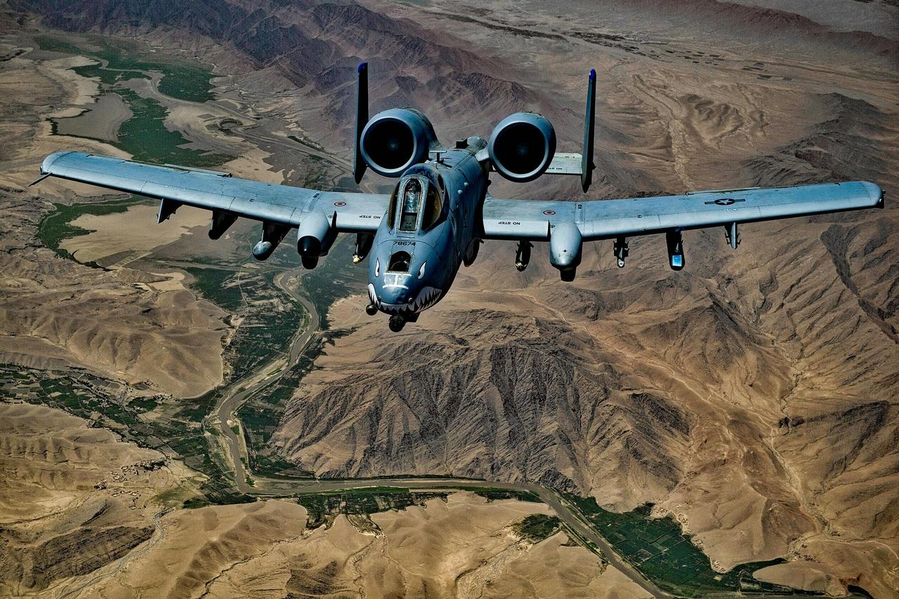
A-10 Thunderbolt II (pexels)
Commonly known by its nickname "Warthog" due to its aggressive appearance and rugged durability, this platform was developed by Fairchild Republic and first entered active service in 1976. The primary mission of the A-10 platform is to destroy enemy armored units, tanks, and fortified ground targets during conventional conflict, thereby preserving the operational capability of friendly ground forces.
Following the experiences of World War II and the Korean War, the United States Air Force doctrine prioritized strategic bombing and air superiority missions. Air Force leadership argued that high-speed, multirole fighter aircraft (F-series) could fulfill close air support roles when needed. However, the Vietnam War in the 1960s revealed serious gaps in this approach. Aircraft such as the F-105 and F-4, which were large and jet-powered, struggled to detect ground targets due to their inability to fly slowly at low altitudes, could not operate effectively in poor weather, and were highly vulnerable to intense light weapons and anti-aircraft fire. Although propeller-driven surplus aircraft such as the T-28 and A-1 Skyraider provided temporary solutions, losses mounted rapidly against increasing threats from anti-aircraft artillery (AAA) and radar-guided anti-aircraft guns.
During the same period, the United States Army (Army) began investing in sophisticated and heavily armed helicopter programs such as the AH-56 Cheyenne to develop air mobility tactics. This initiative created confusion over roles and responsibilities between the two services, as existing military doctrine assigned responsibility for fixed-wing close air support aircraft exclusively to the Air Force. The 1966 Johnson-McConnell Agreement resolved this by having the Army transfer large fixed-wing transport aircraft to the Air Force, while the Air Force accepted responsibility for helicopter-based fire support and committed to developing a more effective, affordable, and specialized CAS aircraft【1】.
In this political and operational context, under the directive of Air Force Chief of Staff General John McConnell, the "A-X" (Attack Experimental) program was officially launched on December 22, 1966. The program's primary objective was to develop a platform with high munition capacity, long loiter time over the battlefield, high maneuverability at low speeds, and maximum survivability against ground fire. In 1970, with a budget approved by David Packard, the program entered the prototype competition phase. The competition pitted Northrop's YA-9A prototype against Fairchild Republic's YA-10A prototype. After comprehensive flight tests and weapons evaluations in late 1972, the YA-10A design was declared the winner due to its superiority in ground support accessibility, turret placement, and manufacturing simplicity.
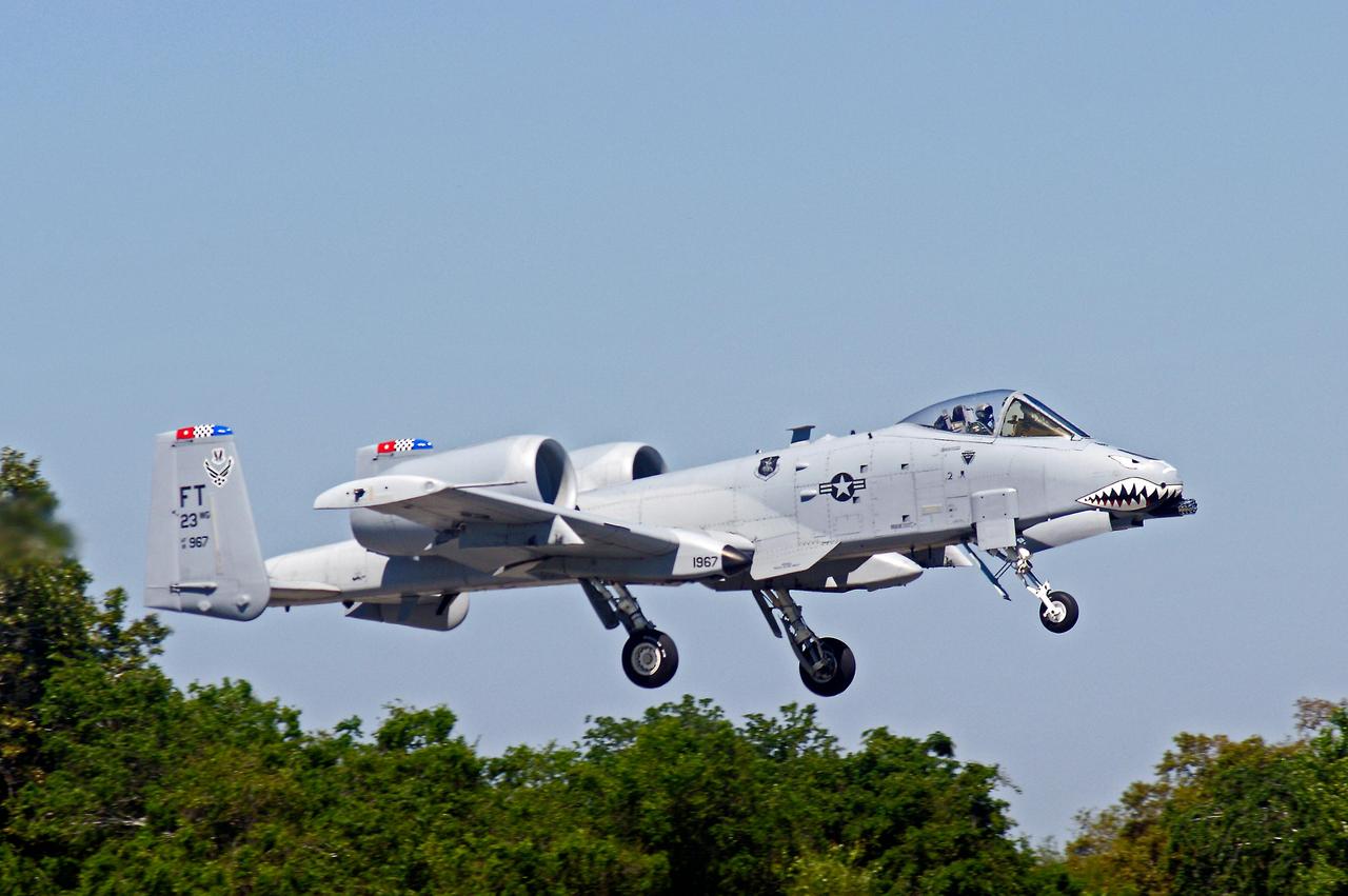
A-10 Thunderbolt II (Phyllis Lilienthal)
The A-10 Thunderbolt II platform was engineered entirely around an asymmetric and robust design philosophy tailored for low-altitude combat under intense air defense threats. The aircraft's fuselage was constructed using flat and angular panels to avoid complex manufacturing geometries, thereby reducing costs and facilitating field maintenance.
The aircraft's geometric dimensions are as follows: a wingspan of 17.42 meters, a fuselage length of 16.16 meters, and a height of 4.42 meters【2】. With an empty weight of approximately 13,154 kilograms (29,000 pounds), the platform can achieve a maximum takeoff weight of 22,950 kilograms (51,000 pounds) when fully loaded【3】【4】. This high margin enables the aircraft to carry not only its internal fuel capacity (7,257 kg / 16,000 pounds) but also a substantial amount of munitions on its external pylons. The A-10 has a total of eleven external pylons—eight under the wings and three under the fuselage—with a combined munition capacity of up to 7,200 kilograms (16,000 pounds).
The engine configuration of the A-10 is one of the most unusual and functionally optimized in aviation history. Two General Electric TF34-GE-100 turbofan engines, each producing 9,065 pounds of static thrust at sea level, are mounted independently on the rear fuselage, just above the wings. These high-bypass-ratio engines enable the aircraft to reach a maximum speed of 420 miles per hour (approximately Mach 0.56)【5】. The primary engineering rationale for positioning the engines high and away from the fuselage includes:
Aerodynamically, the A-10 features a straight, wide wing designed to generate high lift at low speeds. This wing configuration enables the aircraft to execute sharp turns (high instantaneous turn rates) and conduct successive attacks without losing visual contact with targets, even in low cloud ceilings below 1,000 feet (303.3 meters) and visibility as low as 1.5 miles (2.4 kilometers)【6】【7】.
The aircraft's primary weapon system, around which the entire airframe is essentially built, is the 30 mm GAU-8/A Avenger seven-barrel Gatling gun developed by General Electric. This weapon system, including its ammunition feed drum and hydraulic motor, occupies nearly half of the aircraft's nose section and has a total weight of 1,762 kilograms (3,885 pounds)【8】. To align the gun's bore axis with the aircraft's centerline, the nose landing gear is slightly offset to the right, preventing the massive recoil force (approximately 45 kN) from disrupting flight stability or causing nose yaw during firing.
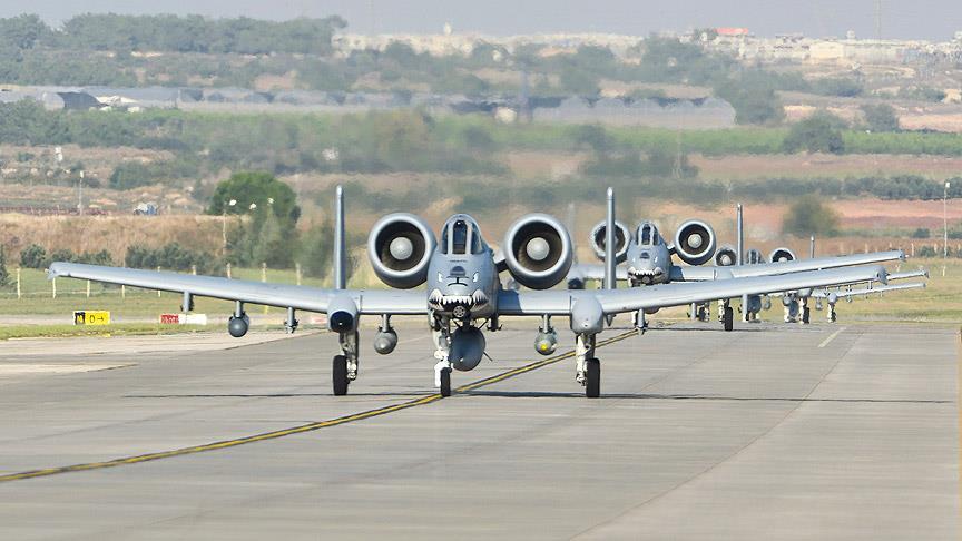
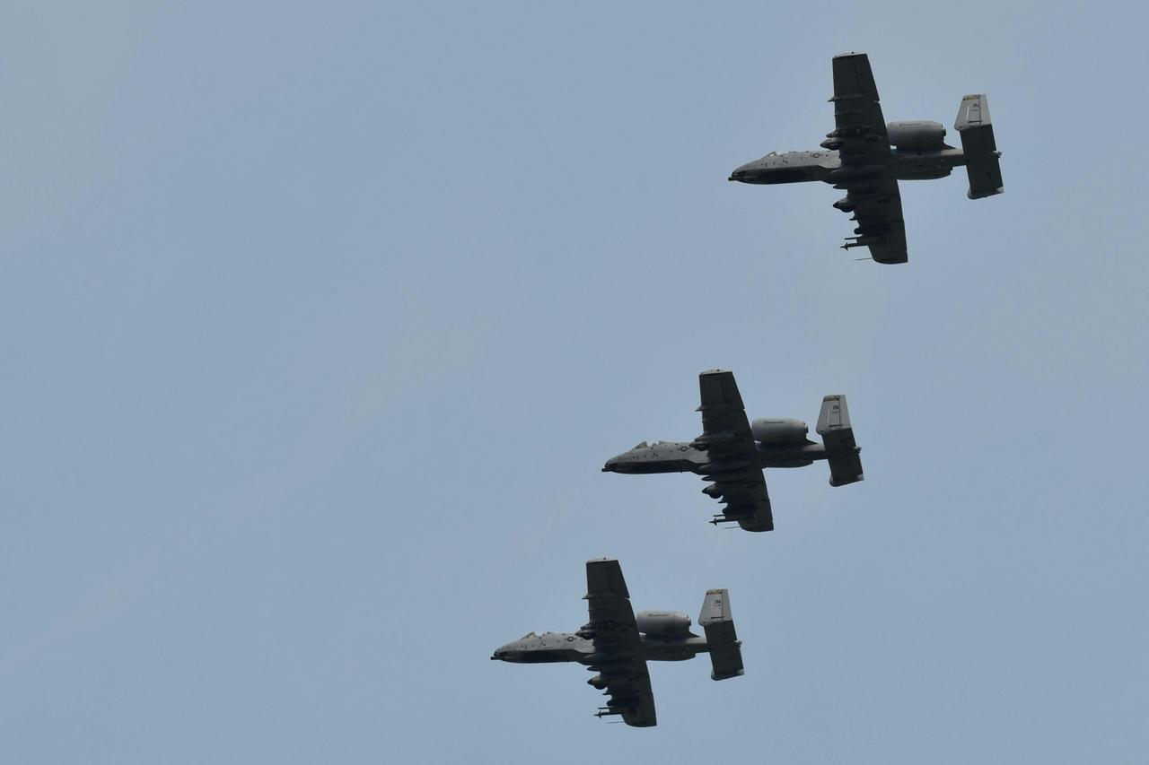
A-10 Thunderbolt IIs at Incirlik Air Base (Anadolu Ajansı)
The GAU-8/A system has a rate of fire of 3,900 rounds per minute. The primary munition configuration consists of a combination of depleted uranium (DU) armor-piercing incendiary (API) rounds, which directly determine tank-killing effectiveness, and high-explosive incendiary (HEI) rounds【9】. Due to their high kinetic energy and density, these 30 mm rounds can penetrate and destroy the turret armor and upper armor layers of main battle tanks. Plastic bonded bands are used on the rounds to extend barrel life and reduce friction. To prevent toxic and flammable gases generated during firing from entering the engine and causing compressor stalls, potassium nitrate suppressant has been added to the propellant mixture, and glass-washing mechanisms have been integrated into the nose section.
The A-10 Thunderbolt II is the platform with the highest level of passive protection in modern aviation history. The cockpit floor and side walls are protected by a "titanium bathtub" composed of titanium armor plates ranging in thickness from 0.5 to 1.5 inches (12.7 mm to 38.1 mm), weighing approximately 544 kilograms. This armored tub provides complete protection for the pilot and critical flight control electronics against direct hits from 23 mm anti-aircraft shells【10】.
The aircraft's flight control surfaces (ailerons, elevators) are actuated by dual hydraulic systems that fully redundantly back each other. In the event both hydraulic systems fail or lose pressure, the pilot can manually switch to a mechanical cable system (manual reversion mode) by pulling a lever in the cockpit. This manual mode allows the pilot to return to base using only physical strength to control the control surfaces without hydraulic power. The aircraft's self-sealing fuel tanks are located in protected areas within the fuselage and are insulated with specialized reticulated foam blast-suppression linings on both inner and outer surfaces to prevent explosion upon impact. The twin vertical tail design ensures directional stability even if one vertical stabilizer is completely lost.
The initial production model, the A-10A, featured a simple avionics architecture designed for visual flight conditions and lacked advanced radar systems. At that time, the system included only basic communication units, VFR navigation equipment, and the Pave Penny pod for tracking laser-designated targets. Over time, the platform underwent the following electronic modernization phases:
Although the A-10 Thunderbolt II program was conceived with international export strategies from its inception and the manufacturer Fairchild actively pursued sales to foreign nations, the platform has an exceptionally unique user profile globally.
The sole operator of the A-10 Thunderbolt II worldwide is the United States. Due to the aircraft's strategic mission profile (close air support) and high logistical requirements, the United States has retained the platform exclusively within its own Air Force and has never exported it to any foreign country. Within the U.S. Armed Forces, A-10 aircraft are operationally managed across three main components:
The A-10 has never been incorporated into the military inventory of any foreign allied nation. Fairchild, the manufacturer, pursued export sales of over seventy A-10 aircraft to allied countries during the 1980s to ensure program continuity, but these efforts failed due to financial, political, and doctrinal reasons. Western European allies (NATO countries) prioritized multirole jet aircraft (F-16, Tornado, etc.) in their air defense doctrines and were unwilling to allocate budgets to a single-mission specialized attack aircraft. Consequently, the platform remains one of the rare strategic systems in military aviation history to be operated solely by its country of origin.
The serial production of the A-10 platform ended in 1984 after 713 aircraft were manufactured【11】. The most significant technical crisis encountered during the aircraft's service life emerged in the areas of metal fatigue and structural integrity.
The A-10 was originally designed with a service life target of 6,000 flight hours【12】. However, Flight Loads and Environmental Survey (L/ESS) studies conducted in the late 1970s revealed that the aircraft's actual operational profile in service was significantly more severe and fatiguing than anticipated during design. Full-scale fatigue tests conducted in 1979 under the newly identified "Spectrum 3" loading profile detected severe fatigue cracks in the main load-bearing structure, particularly at Wing Station 23 (WS 23) and the wing center panels.
The Air Force responded by transitioning to a "Thick Skin" wing configuration, increasing the thickness of the lower skin on wing center panels for aircraft produced from the 582nd unit onward. This modification extended the service life of these aircraft to 8,000 hours. However, hundreds of early-production aircraft continued to operate with "Thin Skin" wings, creating a long-term sustainability crisis【13】.
The 1993 Force Structural Maintenance Plan (FSMP) mandated periodic non-destructive inspections (X-ray and ultrasonic) of all aircraft at fatigue-sensitive locations, particularly the WS 23 region. However, this plan was not fully implemented by operational units; maintenance crews preferred to inspect only a small sample group using Analytical Condition Inspection (ACI) rather than screening the entire fleet. The 1995 Base Realignment and Closure (BRAC) decision, which relocated the A-10 System Program Office from Sacramento (McClellan Air Force Base) to Ogden (Hill Air Force Base), resulted in the loss of 80% of the office's experienced engineering and technical staff. This administrative disruption, combined with the exit of the original equipment manufacturer (OEM) Fairchild from the aerospace sector, caused the fleet's structural health monitoring to collapse entirely.
To extend the A-10 fleet's service life to 2028, the Air Force launched the comprehensive structural renewal program "HOG UP" in 1999. However, rather than being executed as a true modernization project, HOG UP was managed as a large-scale repair program designed to bypass administrative approval processes. Historical ACI crack data was not fully accounted for in this process. In 2003, an independent "Red Team" review panel concluded that the technical foundations of HOG UP were flawed and that the aircraft's true fatigue condition had not been verified. The feared scenario soon materialized: a test wing subjected to HOG UP procedures failed catastrophically (sudden and permanent fragmentation) before reaching the target lifespan of 16,000 hours. In depot inspections, 30% of thin-skin wings were found to have irreparable WS 23 cracks.
After it became clear that the wing structures could not be salvaged through patching or organic repair methods, the United States Air Force conducted a comprehensive Business Case Analysis (BCA) in 2005. The analysis determined that attempting to repair the old wings would cost $4.6 billion, whereas manufacturing entirely new zero-hour wings would cost only $1.72 billion. The Air Force urgently established a budget for new wing procurement. Due to the absence of original technical drawings, three-dimensional computer models capturing the as-built geometry of the aircraft were first developed. In 2007, the aerospace giant Boeing won the competitive bid. Under the resulting contract, Boeing began producing entirely new thick-skin replacement wings for the A-10 fleet. The integration of Boeing-manufactured new wings onto Fairchild-built fuselages, under the chief engineering leadership of Lockheed Martin, became one of the most complex and multi-stakeholder life-extension operations in military sustainability history【14】.
Accessed November 26, 2025. https://www.aa.com.tr/tr/kultur/ahlatta-acilan-kurslarla-geleneksel-tas-isciligi-yasatiliyor/3116279.
Accessed November 26, 2025. https://www.aa.com.tr/tr/kultur/ahlatta-acilan-kurslarla-geleneksel-tas-isciligi-yasatiliyor/3116279.
Accessed November 26, 2025. https://www.aa.com.tr/tr/kultur/ahlatta-acilan-kurslarla-geleneksel-tas-isciligi-yasatiliyor/3116279.
Accessed November 26, 2025. https://www.aa.com.tr/tr/kultur/ahlatta-acilan-kurslarla-geleneksel-tas-isciligi-yasatiliyor/3116279.
Accessed November 26, 2025. https://www.aa.com.tr/tr/kultur/ahlatta-acilan-kurslarla-geleneksel-tas-isciligi-yasatiliyor/3116279.
Anadolu Ajansı. "İncirlik Hava Üssü'nde Hareketlilik." Accessed May 25, 2026.
Cradle of Aviation Museum. "Jet Gallery: Fairchild-Republic A-10 Thunderbolt II." Accessed May 25, 2026.
GlobalSecurity.org. "A-10/OA-10 Thunderbolt II Design and Specifications." Accessed May 25, 2026.
Hill Aerospace Museum. "Aircraft Collection: Fairchild A-10A Thunderbolt II." Accessed May 25, 2026.
Jacques, Daniel R. and Dennis D. Strouble. "A-10 Thunderbolt II (Warthog) Systems Engineering Case Study." Air Force Center for Systems Engineering (AFIT/SY), Air Force Institute of Technology, 2010, pp. 1-84. Accessed May 25, 2026.
K O'Shaughnessy. "A-10 Thunderbolt II". Pexels (photograph). Accessed May 25, 2026. https://www.pexels.com/tr-tr/fotograf/gokyuzu-ucan-askeri-hava-kuvvetleri-11704999/
Lilienthal, Phyllis. "Florida-attached Titusville, A-10 Thunderbolt II military aircraft flying low, showcasing its distinctive features." Pexels (photograph). Accessed May 25, 2026. https://www.pexels.com/tr-tr/fotograf/a-10-thunderbolt-ii-titusville-uzerinde-ucuyor-33078173/
U.S. Air Force Fact Sheet. (2020). "A-10C Thunderbolt II." Air Combat Command Public Affairs Office. Accessed May 25, 2026.
https://www.aa.com.tr/tr/turkiye/incirlik-hava-ussunde-hareketlilik/449574
[1]
Daniel R. Jacques and Dennis D. Strouble, "A-10 Thunderbolt II (Warthog) Systems Engineering Case Study," Air Force Center for Systems Engineering (AFIT/SY), Air Force Institute of Technology, 2010, p. 8, Access Date: May 25, 2026,https://apps.dtic.mil/sti/tr/pdf/ADA530838.pdf
[2]
U.S. Air Force Fact Sheet, "A-10C Thunderbolt II," Air Combat Command Public Affairs Office, 2020, p. 1, Access Date: May 25, 2026,https://www.af.mil/About-Us/Fact-Sheets/Display/Article/104490/a-10c-thunderbolt-ii/
[3]
Daniel R. Jacques and Dennis D. Strouble, "A-10 Thunderbolt II (Warthog) Systems Engineering Case Study," Air Force Center for Systems Engineering (AFIT/SY), Air Force Institute of Technology, 2010, p. 11, Access Date: May 25, 2026,https://apps.dtic.mil/sti/tr/pdf/ADA530838.pdf
[4]
U.S. Air Force Fact Sheet, "A-10C Thunderbolt II," Air Combat Command Public Affairs Office, 2020, p. 1, Access Date: May 25, 2026,https://www.af.mil/About-Us/Fact-Sheets/Display/Article/104490/a-10c-thunderbolt-ii/
[5]
U.S. Air Force Fact Sheet, "A-10C Thunderbolt II," Air Combat Command Public Affairs Office, 2020, p. 2, Access Date: May 25, 2026,https://www.af.mil/About-Us/Fact-Sheets/Display/Article/104490/a-10c-thunderbolt-ii/
[6]
Daniel R. Jacques and Dennis D. Strouble, "A-10 Thunderbolt II (Warthog) Systems Engineering Case Study," Air Force Center for Systems Engineering (AFIT/SY), Air Force Institute of Technology, 2010, p. 11, Access Date: May 25, 2026,https://apps.dtic.mil/sti/tr/pdf/ADA530838.pdf
[7]
U.S. Air Force Fact Sheet, "A-10C Thunderbolt II," Air Combat Command Public Affairs Office, 2020, p. 2, Access Date: May 25, 2026,https://www.af.mil/About-Us/Fact-Sheets/Display/Article/104490/a-10c-thunderbolt-ii/
[8]
Daniel R. Jacques and Dennis D. Strouble, "A-10 Thunderbolt II (Warthog) Systems Engineering Case Study," Air Force Center for Systems Engineering (AFIT/SY), Air Force Institute of Technology, 2010, p. 24, Access Date: May 25, 2026,https://apps.dtic.mil/sti/tr/pdf/ADA530838.pdf
[9]
Daniel R. Jacques and Dennis D. Strouble, "A-10 Thunderbolt II (Warthog) Systems Engineering Case Study," Air Force Center for Systems Engineering (AFIT/SY), Air Force Institute of Technology, 2010, p. 26, Access Date: May 25, 2026,https://apps.dtic.mil/sti/tr/pdf/ADA530838.pdf
[10]
Daniel R. Jacques and Dennis D. Strouble, "A-10 Thunderbolt II (Warthog) Systems Engineering Case Study," Air Force Center for Systems Engineering (AFIT/SY), Air Force Institute of Technology, 2010, p. 35, Access Date: May 25, 2026,https://apps.dtic.mil/sti/tr/pdf/ADA530838.pdf
[11]
Daniel R. Jacques and Dennis D. Strouble, "A-10 Thunderbolt II (Warthog) Systems Engineering Case Study," Air Force Center for Systems Engineering (AFIT/SY), Air Force Institute of Technology, 2010, p. 42, Access Date: May 25, 2026,https://apps.dtic.mil/sti/tr/pdf/ADA530838.pdf
[12]
Daniel R. Jacques and Dennis D. Strouble, "A-10 Thunderbolt II (Warthog) Systems Engineering Case Study," Air Force Center for Systems Engineering (AFIT/SY), Air Force Institute of Technology, 2010, p. 46, Access Date: May 25, 2026,https://apps.dtic.mil/sti/tr/pdf/ADA530838.pdf
[13]
Daniel R. Jacques and Dennis D. Strouble, "A-10 Thunderbolt II (Warthog) Systems Engineering Case Study," Air Force Center for Systems Engineering (AFIT/SY), Air Force Institute of Technology, 2010, p. 54, Access Date: May 25, 2026,https://apps.dtic.mil/sti/tr/pdf/ADA530838.pdf
[14]
Daniel R. Jacques and Dennis D. Strouble, "A-10 Thunderbolt II (Warthog) Systems Engineering Case Study," Air Force Center for Systems Engineering (AFIT/SY), Air Force Institute of Technology, 2010, p. 60, Access Date: May 25, 2026,https://apps.dtic.mil/sti/tr/pdf/ADA530838.pdf


Type(s) | Close Air Support (CAS) and Forward Air Control (FAC) Aircraft | ||||||||
|---|---|---|---|---|---|---|---|---|---|
Active User Countries | United States (USAF, AFRC, ANG) only | ||||||||
Internal Gun System | 1 x 30 mm GAU-8/A Avenger Seven-Barrel Gatling Gun | ||||||||
Service Ceiling | 45,000 feet (13,636 metres) | ||||||||
Maximum Flight Speed | 420 miles per hour (Mach 0.56) | ||||||||
Maximum Payload Capacity | 7,200 kg (16,000 pounds) | ||||||||
Maximum Takeoff Weight | 22,950 kg (51,000 pounds) | ||||||||
Engine Thrust | 9,065 pounds per engine | ||||||||
Powerplant | 2 x General Electric TF34-GE-100 Turbofan | ||||||||
Crew Configuration | 1 (Pilot) | ||||||||
Year of First Entry into Service | March 1976 | ||||||||
Current Primary Operator/Operator | Lockheed Martin / Northrop Grumman / Boeing | ||||||||
Designer/Original Manufacturer | Chrysler Defense / Fairchild Republic Co. | ||||||||
No Discussion Added Yet
Start discussion for "A-10 Thunderbolt II" article
History and Emergence of the Requirement
Detailed Technical Specifications and Design Architecture
Dimensions, Weight, and Payload Capacity
Propulsion and Aerodynamic Performance
Internal Weapon System: GAU-8/A Avenger
Armor, Protection, and Redundant Safety Infrastructure
Electronic and Avionics Infrastructure Development
Countries Operating the A-10 Thunderbolt II
United States (Sole Active Operator)
Status of Other Countries and Export Attempts
Structural Life Cycle, Sustainability Challenges, and Wing Replacement Program
Early Structural Cracks and Spectrum Concerns
Breakdowns in Sustainability Management and the BRAC Decision
HOG UP Program and Catastrophic Wing Failure
New Wing Procurement Competition and the Boeing Era